

Where it fits
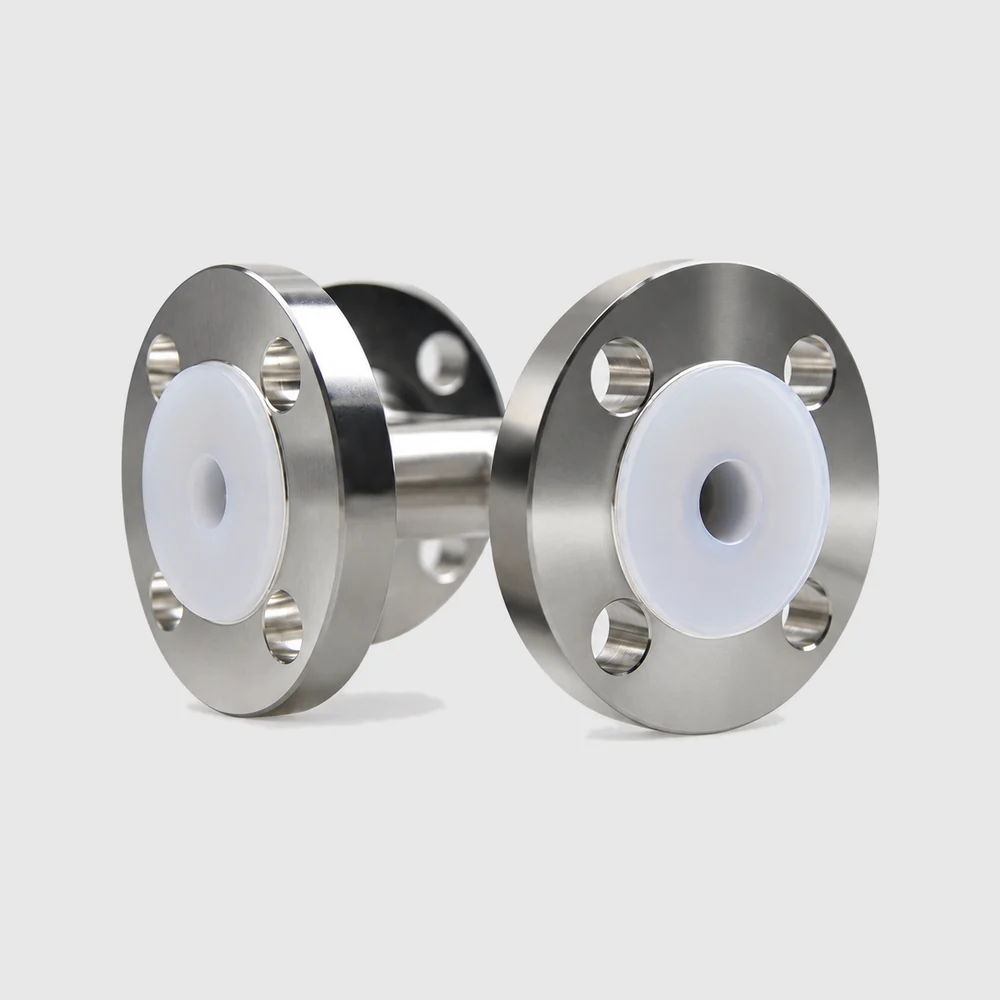
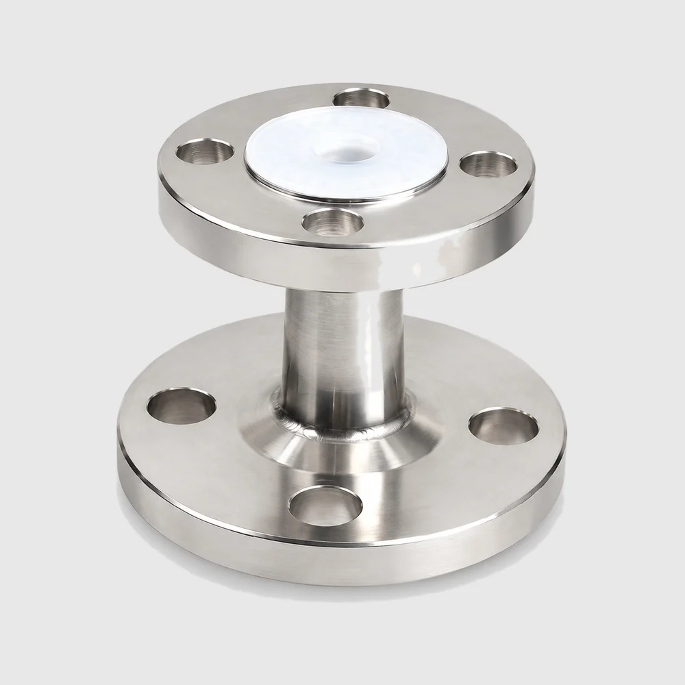
These flanged tees and reducers sit on the transfer lines of the chemical delivery system (CDS) in a semiconductor fab and on the ultrapure fluid lines of display and solar wet-process lines, where they handle branching and changes of pipe size. Those lines are mostly flanged, lined steel pipe: the metal outside carries line pressure, supports and knocks, and the PFA inside keeps the chemistry away from the metal.
Tees and reducers look like supporting parts, but they are where flow changes direction and velocity, and where the lining is most likely to be stressed by misaligned installation or thermal movement. If the whole line is to stay fluoropolymer-wetted, the lining on these fittings has to match the pipe and valves.
Key characteristics
The body is 316L stainless steel lined with high-purity PFA, so only PFA is wetted and ionic contamination is very low. It resists acids, alkalis, chemicals, corrosion and steam, so one set of fittings can serve many chemistries instead of stocking a different material for each.
- Design pressure vacuum to 1.0 MPa (at 20 °C), so the negative pressure seen during suction and drain-down is within the rating.
- Design temperature -30 to +150 °C, covering hot chemicals and steam.
- The PFA resin can be specified to suit the cleanliness requirement, as an ultra-pure grade from a leading international producer or a cost-effective high-purity grade; material certificates are available and the series is FDA compliant.
Choosing between options
Decide the connection first, then the configuration. Flanged fittings suit fixed lines and equipment nozzles built around flanges; if the line is a Tri-Clamp system or is opened often for cleaning, look at the PFA-lined Tri-Clamp fittings instead.
| Item | Equal tee (T) | Reducer (RC) |
|---|---|---|
| Purpose | Branching and merging on a line of one size | Stepping a main line down to a smaller branch or equipment port |
| Sizes | DN15, DN20, DN25, DN40, DN50 | DN80 × DN40, DN80 × DN20, DN50 × DN40, DN50 × DN25, DN40 × DN25, DN25 × DN20 |
| Flange standard | HG/T 20592 | HG/T 20592 or JIS 10K |
| Pressure / temperature | Vacuum to 1.0 MPa (at 20 °C) / -30 to +150 °C | Vacuum to 1.0 MPa (at 20 °C) / -30 to +150 °C |
The flange standard must match the line and equipment it bolts to: HG/T 20592 and JIS 10K have different bolt patterns and cannot be mixed. Japanese equipment is usually JIS 10K, so check the equipment drawing or nameplate before ordering.
Operation & change-out
On a lined fitting the flange sealing face is PFA, so keep tools off it during installation. Align the pipework before bolting up and never use the bolts to pull a misaligned spool into place; that stress ends up concentrated in the lining. Tighten in a cross pattern in stages, and because a plastic sealing face creeps slightly after thermal cycling, re-torque once after the first hot run.
Gasket selection follows your piping specification; state it at enquiry. In routine checks, look for weep marks at the flange edge and for discoloration or rust spots on the shell, which usually signal that the lining has been permeated or damaged.